Mitsubishi Crank Trigger Kit - Pro Series
This document outlines the recommended procedure for installing the PRP Pro Series Ignition Trigger Kit to suit the Mitsubishi 4G63 Motor.
This Upgraded, Motorsport Specification Ignition Trigger Systems is designed with higher engine position data resulting for increased accuracy at higher power and RPM levels. This increase in data allows your ECU to know more and assume less, providing for increases in performance, engine dynamics and safety.
Following the instructions precisely ensures optimal performance and longevity of the pump. Deviating from these recommendations, including using unapproved components or wiring setups, will void the warranty on the pump motor.
Pre-Installation Requirements
- Balance Shaft Delete. As is common with high performance 4G63 builds, the balance shaft must be deleted in order for this kit to be used. The PRP Billet Crank Sensor Mount locates in the area at the front of the engine where the OE Balance shaft drive would be located.
- Aftermarket ECU. This PRP Ignition Kit is designed to work with an aftermarket ECU where a non OEM trigger pattern is utilized. As such, the OE ECU will not be suitable.
- Programmable ECU. This PRP trigger kit, while based around a common tooth count requires the ability to set and adjust the trigger settings within the ECU. An ECU with these functions is required to use this trigger kit and some Plug and Play ECU's where this feature is not available, will not be suitable
- ECU Calibration. Your ECU will require recalibration to suit this new ignition pickup system and will not be able to be driven without tuning to suit. Engine position is a critical input into any ECU and any changes, including an improvement in data resolution should be accounted for and calibrated to suit.
- Access and Installation. If the engine is fitted to the vehicle, you will require access to front of the engine including removal of the lower timing cover and access to the crank. The timing belt will need to be removed, along with the lower timing belt gear located on the crank. Please follow OE instructions for all removal and replacement of timing covers, belt and gears.
- Link G4X Fury base setting -70 degrees
Ignition Trigger Specifications
Trigger Pattern 36 - 2
Sensor Type Hall Effect
Connectors Deutsche
Installation Guidelines
1. R&R Timing Belt and Crank Gear
- Removal and Replacement of the Timing Covers, Timing Belt and Lower Crank Timing Gear is required. Please follow OE guidelines for this process.
- Correct Belt Installation and Alignment is critical for engine safety. Please do not attempt this yourself if you are not confident or experiences with this process including mechanical engine timing etc.
2. Remove OE Crank Angle Sensor and Trigger
- You will need to remove the OR crank angle sensor hardware in order to install the PRP Pro Series Ignition timing Kit.
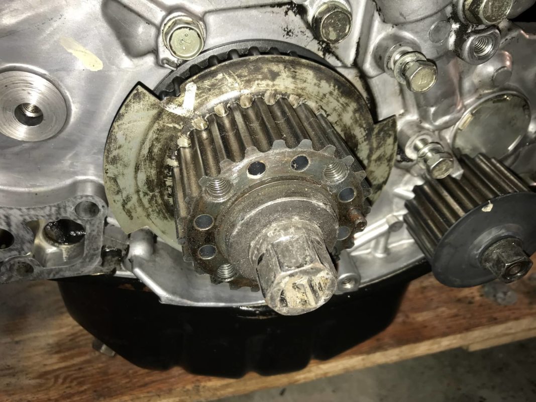
- The Factory Hall effect sensor and dual profile profiled trigger wheel should be removed once the timing covers, timing belt and lower timing belt gear has been removed from the crank.
3. Installation of the PRP Ignition Timing Kit
- The PRP Pro Series Trigger Wheel is a precision made, direct fit component and will slide onto the front of the crank, directly in place of the OE trigger wheel.
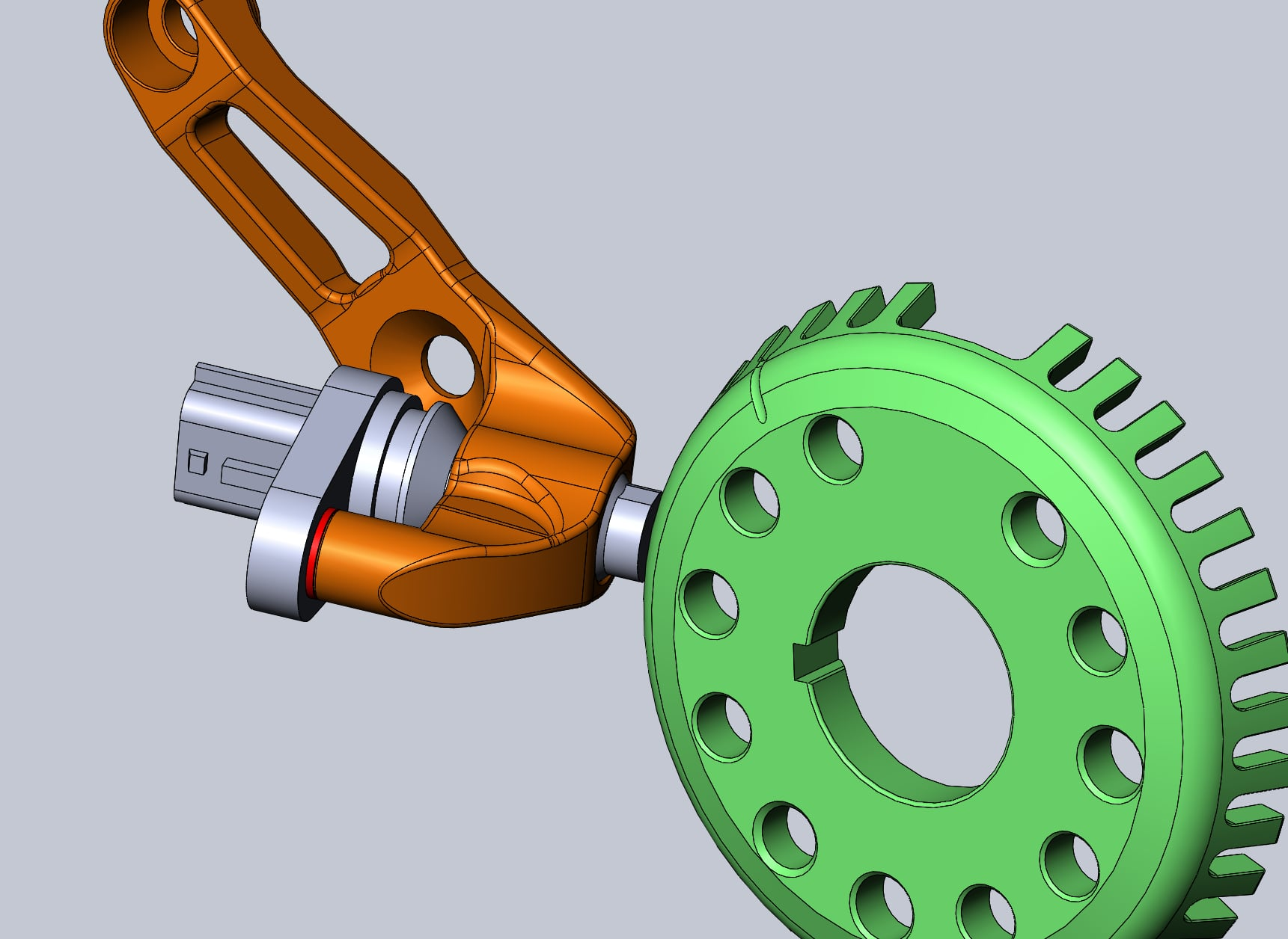
- The PRP Billet Sensor Mount will need to be fitted (Images below). As mentioned, this kit will assume a balance shaft delete has been performed and the mount will locate in an area where the OE balance shaft gear would normally be located.
- The V1 mount shown in yellow, along with the adapter, shown in blue, indicates an adapter we have supplied to the V1 kits. This rotates the orientation of the sensor to ensure clarity of readings in all installations and versions of the OEM Nissan sensor.
- The V2 mount shown in orange, deletes the necessity of an adapter.
- The red spacer is an optional item to ensure the gap between the sensor and crank wheel remains near enough to 1mm. Due to casting tolerance changes, this may be required on some blocks.

4. Wiring in the Sensor
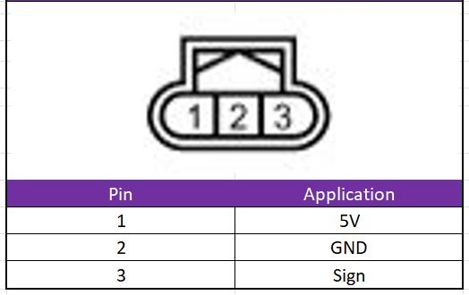
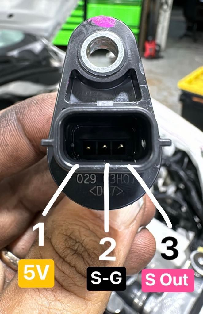
Refer below table outlining the basic pinout of the connector as it relates to the supplied sensor.
* The sensor should be wired directly to the ECU and not using the factory Evo wiring.
*Please Ensure GND is connected to the common ECU Sensor Ground Circuit, Not the vehicle's Earth / Circuit.